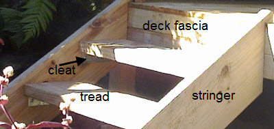
Image courtesy of Sydney Wide Carpenters
There is often a need for steps as an access to a deck or for use between decks with different levels. A basic open stairway consists of the two stringers and two or more treads. The supporting members of a stair are the stringers. These are used in pairs spaced one metre apart (approximately). The overall height of steps from ground line to deck or landing should not exceed one metre.
Important terms
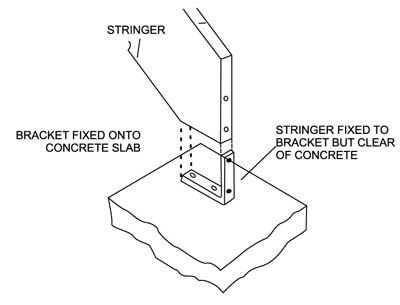
1. Stringer
Stringers are the sides of the steps to which treads are fixed (see image above).
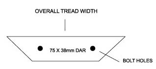
2. Tread
Treads are the actual walking platforms which bridge between two stringers. They are supported by cleats fixed to stringers.
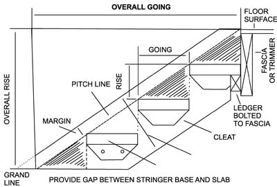
3. Rise
Rise refers to the vertical distance between the upper surfaces of the treads. This is should be uniform over the length of the stairway. In this article, and in many published tables, this term may be used interchangeably with "riser" to indicate the height of each evenly spaced step.
4. Fixing
Fixings attach stringers to the base and upper level of the step. On the ground level the base can be a concrete slab, pathway or paving. At the upper level the fixings may attach to a deck or directly to the side of a house.
First considerations
Unfortunately, there is no set of steps which will fit every location. To provide comfortable and safe steps which comply with Local Government Regulations, each set of steps should be designed to suit the particular application or situation.
Several established rules should be followed if comfortable, safe and approved steps are to be built.
- All risers should be of equal height, and this includes the first riser from he base (or ground) level and the last riser onto the upper level.
- Steps should provide a MINIMUM clear width of 240 mm but a MAXIMUM of 355 mm.
- Although linked to tread width, the RISE should be between 190 mm and 115 mm but a preferred height could be adjusted for agility of the users. (For example, the less agile elderly may prefer a rise of about 145 mm).
- In correctly designed steps the link between "rise" and tread (width) is as expressed
in the Building Code of Australia: NSW Amendment in the following formula:
2R + G should equal between 700 and 550 where R = rise in mm, G = clear tread width in mm.
Tools you will need
|
|
Materials you will need
Timber
For the template: Thin plywood/hardboard/particle board 400 x 200 mm.
For the stringers: 300 x 50 mm DAR/dressed-all-round selected native hardwoods, selected plantation pine, selected to provide relatively straight grained, clear pieces.
For the cleats: 75 x 38 mm DAR, cut to length to suit width of treads (refer to item No. 10). Note that you can also use metal cleats as shown in the picture above.
For the treads: If wide enough for design, the step tread could be of 250 x 50 mm or 300 x 50 mm DAR or made up of two (spaced) pieces each 50 mm (DAR) thick, provided length does not exceed 900 mm.
IMPORTANT! To minimize expansion and shrinkage after installation, seasoned timber should be used if available.
Note particularly that steps which will be exposed to weather and associated moisture absorption, (rain, dew) should be made from timber (species) selected for durability in such conditions such as some mixed hardwoods, preservative treated plantation pine treated for above ground use (Hazard level 3 H3), selected durable hardwoods such as black butt, ironbarks, turpentine, tallowwood, jarrah, kwila (merbau), spotted gum etc. For better performance individual pieces of timber should have the minimum of imperfections which allow moisture (water) to penetrate the timber.
Consult your TABMA timber supplier about suitable available, durable timber for weather-exposed steps.
Hardware
Two galvanised angle-brackets, i50 x 2b x 4 mm or similar to fix foot of steps at ground level.
Coach screws, galvanized, for fixing bracket to stringers.
Loxon or similar concrete fastenings to fix brackets to concrete base slab (if required).
75 x 3.75 mm galvanized bullet head nails, to fix tread to stringers and at cleats.
Two 10 mm galvanized bolts, nuts, washers for each timber cleat used, (or 4 bolts per tread) length of bolt to suit thickness of cleats plus stringers you have selected.
Timber/wood primer (exterior grade if required) to seal end grain of stringers, treads and pre-coat cleats and ledgers.
Selected paints/stains appropriate for application (interior or exterior).
Limitations and precautions
This project sheet is a guide for relatively short stairways only.
For comfortable ascent with longer stairways, limit the step rise as indicated but also provide a landing at the half way point with a maximum of eight steps between “landings” but ensure all risers are the same throughout.
Stairways generally, benefit from hand rails. Regulations require that stairways over 1m or with 5 or more risers, (if not bounded by a wall) have a continuous balustrade, not less than 865 mm above the nosing of the stair tread. Note too that the balustrade/guard rail must prevent, as far as practicable, children climbing over or through.
Step-by-step instructions
1. Start
Measure overall rise or height of steps which will be the vertical distance from the top platform (e.g. decking surface) to the existing patio or pathway or to the proposed new level base.
Example:
• Assume the height H is 640 mm from base to surface of deck.
2. Calculate riser height
Calculate the distance between each step.
Example:
1. Divide steps height, H, by 3 which gives a step height of 213 mm which is too large for comfort...
2. Divide Steps height, H, by 5 which gives a step height of 128 mm which is too small.
Conclusion: 4 rises are needed, each 160 mm high.
3. Calculate clear tread width
Calculate the preferred clear step width with the acceptable riser height calculated in the previous step. (Note that the MINIMUM acceptable clear tread width will be 240 mm.)
Example:
With a riser height of 160 mm, and using the previously mentioned formula (2R + G = 550), it can be calculated that for this example the MINIMUM step-width is 230 mm (impractical & illegal) and the MAXIMUM step-width is 380 mm.
Because wide planks are often difficult to obtain it may be preferable to
select tread widths according to readily available dressed timber size; e.g. dressed widths of 240 mm or 290 mm.
4. Making the first step
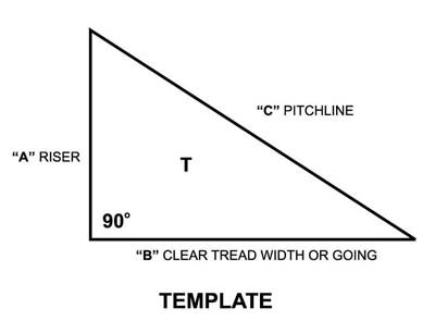
Make a template from the plywood, hardboard or particle board (or thick cardboard) to suit your stair requirements.
Example:
Using the figures calculated in steps 1,2 & 3 cut a template as shown where
A - riser = 160 mm, B - tread = 240 mm (or 290 mm)
and C - pitch lines to be measured, which will be about 289 mm (or 331 mm).
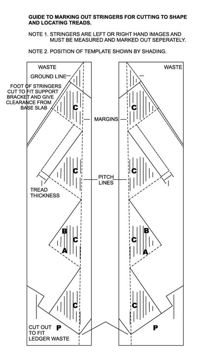
Then, as indicated on the diagram mark the stringers using the template.
Also mark the upper line 'P', which indicates the top vertical line of the stringer (when installed), allowing for full tread width, including any overlap for the topmost tread. With the outline of stringer marked also locate and mark the position of the cut-out for the ledger (if used) as well as the necessary cut away for the fixings used to mount the stringers to the base which should still provide the designed "rise" from base to first tread.
5. Calculate stringer length
Measure C, the pitch length, on your template. Multiply pitch length by the number of risers to give overall length of pitch line.
Example:
When B = 240 mm and A = 160 mm, then C = 289mm. From Step 2 the number of risers is 4. Then total pitch line/stringer length is 4 x 289 = 1156 mm (for B = 290 mm pitch line length is 1324 mm).
6. Purchase timber
On the basis of using 50 mm thick DAR (dressed-all-round) timber for both stringers and treads.
Important! Order multiples of 300 mm LENGTHS for stringers but assume acceptable tread lengths of 900 mm.
Example:
Stringers:
2 required (minimum tread width of 240 mm) 300 x 50 mm DAR, 2/1.2*
Treads: 3 required (for minimum tread width 240 mm) 250 x 50 mm DAR, 6/900 mm *
Cleats: 6 required (for minimum tread width 240 mm) 75 x 38 mm DAR, 6/240 mm *
Ledger: 1 required
75 x 50 mm DAR, 1/1.2 m *
* Merchant will supply sufficient material from which these sizes can be cut.
7. Cut two stringers
Calculated length from 300 x 50 mm DAR purchased.
Example: 1156 mm each piece, at least.
8. Mark out stringers
The essential tool in this task is the template made in Step 4. The first task is to mark a margin line which, for example, could be 50 mm (see diagram) away from the upper edge of both stringers. Then, as indicated on the diagram, mark the stringers out using the template.
Mark also the upper line 'P' which indicates top vertical line of the stringer (when installed) allowing for full tread width, including any overlap for the topmost tread. With the outline of stringer marked also locate and mark position of the cut-out for ledger (if used) as well as the necessary cut away for the fixings used to mount the stringers to the base slab/pathway which should still provide the designed "rise" from base to first tread.
9. Cut out stringers
Cut out the stringers as marked. Prime or otherwise seal all exposed end grain.
10. Cut cleats
If using timber cleats cut them to the pattern shown below and prime or seal if steps are to be exposed to weather. Fasten in position using two galvanised bolts, nuts and washers. Pre-bore bolt holes not less than 50 mm from ends of cleats.
Metal cleats need to be screwed into place and should be galvanised to withstand the outdoors.
11. Fix angle bracket at foot
With stringers held in final position as a guide, the location of the galvanised angle bracket can be fixed and the necessary Loxon, Ramset or similar fastenings inserted in the existing patio floor or path. If new concrete slab is required this should be level and sufficiently wide, at least, to form another standard size ground level tread and located to conform to the step/tread pattern.
Example:
Tread length 900 mm
Minimum concrete slab 1200 x 300 x 100 mm Distance between centres of brackets and stringers 945 mm.
12. Cut ledger
Cut ledger to a length sufficient to project about 150 mm on each side of the stringer.
Example:
For 900 mm tread width this would require a ledger 1300 mm long.
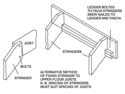
13. Fix ledger in place
Fix ledger in place on fascia or timber board or on edge of deck using three galvanised bolts, nuts and washers or coach screws as appropriate. Pre-bore bolt holes not less than 50 mm from end of ledger.
14. Fix stringers to angle brackets
Fix stringers to angle brackets at foot of steps and screw nail to ledger ensuring that they are located parallel, vertical, and at spacing as required for treads. Note: Stringers do not contact concrete slab. Dampcourse can be fixed if desired between the concrete and the stringers.
15. Cut treads to length
Cut treads to length, slightly round or bevel each Id long edge.
16. Spot prime
Spot-prime or otherwise seal end grain of each tread, particularly where steps will be exposed to weather.
17. Fix treads in place
Fix treads in place, nailing through stringer into end of tread and through pre-drilled holes into the cleats. Use three 75 x 3.75 mm galvanised bullet head nails into each end of tread and through tread into cleats.
18. Sand or plane off all sharp corners
Punch and putty nail holes if desired. Clean up surfaces as required and apply appropriate exterior (or interior) stains or paints as instructed by the paint manufacturer.
(Note: The long term durability of those timber structures which are exposed to weather is improved by application of exterior quality water repellents, stains or paints. These should be regularly inspected and maintenance coats applied as necessary).
Author and copyright
This brochure was prepared with the assistance and co-operation of the Timber Development Association NSW Ltd. For further information see www.timber.net.au.
Copyright Owner: Timber and Building Materials Association (NSW) Limited
Disclaimer
This article was originally written by the Timber and Building Materials Association (AUST) Limited (TABMA). It has since been edited by Home Design Directory (HDD) staff. TABMA and its members (and the HDD) believe this publication is an invaluable guide to those interested in building timber steps on their own, but the Association & HDD cannot guarantee that every statement is without flaw. Therefore, the Association and its members hereby disclaim all liability for errors or omissions of any kind, whether they be negligent or otherwise, or for any loss, damage or other consequence which may arise from any person relying on information stated in this publication.
Related articles
Build your own deck in 6 easy steps (DIY deck)